
Alternatives #
Before I bought the Ender 3 Pro 3D printer I was trying hard to figure out how to create all of the fixtures out of wood. The first design I created barely fit the servos and gears. I hadn’t even got to the rest of the components and this was while I was going to be putting it all in the top.
After my printer came I found Thingiverse and found it had brackets and cases for Arduinos and Raspberry Pis. All other parts I designed using the hobbiest version of Fusion 360 for Personal Use. Below is a list of the files, (F3D is the Fusion 360 file and STL is the stereolithography file used by most 3D printers).
Parts List #
| Qty | Part | File(s) |
|---|---|---|
| All Files Zip |  |
|
| 7 | Arduino Nano Bracket |  , ,  |
| 7 | Arduino Wire Guide | , |
| 1 | Button Plate | , |
| 1 | Raspberry Pi Case Bottom | |
| 1 | Raspberry Pi Case Top | , |
| 4 | Servo Board Standoff | , |
| 1 | Servo Bracket | , |
| 7 | Gear Cover (differing diameters for shafts) | |
| - Ravenclaw | , |
|
| - Hufflepuff | , |
|
| - Gryffindor | , |
|
| - Slytherin | , |
|
| - Hour | , |
|
| - Minute | , |
|
| - Second | , |
|
| 7 | Servo Gear | , |
| 7 | Step Gear | , |
| 7 | Idle Gear | , |
| 7 | Clock Shaft Gear (differing diameters for shafts) | |
| - Ravenclaw | , |
|
| - Hufflepuff | , |
|
| - Gryffindor | , |
|
| - Slytherin | , |
|
| - Hour | , |
|
| - Minute | , |
|
| - Second | , |
|
| 1 | Bearing Cover | , |
| 7 | Clock Hands (various designs) | |
| - Ravenclaw | , |
|
| - Hufflepuff | , |
|
| - Gryffindor | , |
|
| - Slytherin | , |
|
| - Hour | , |
|
| - Minute | , |
|
| - Second | , |
|
| 2 | Conduit Bracket | , |
| 1 | Pendulum Bracket | , |
| 2 | Weight Servo Bracket | , |
| 2 | Weight Servo Bracket Cover | , |
| 2 | Weight Sprocket | , |
Other Models List #
These where models for physical parts. They were used to help get the sizing correct.
| Part | File(s) |
|---|---|
| Raspberry Pi 3 B+ | |
| AdaFruit Servo Hat | |
| Parallax 360 Servo | |
| Relay Board | |
Arduino Nano Brackets #
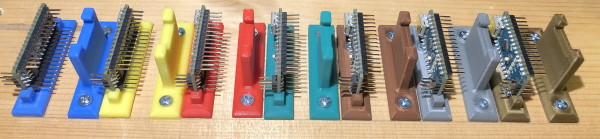
For the Arduino brackets I started using DaveGadgeteer’s design from Thingiverse but I quickly ran into troubles as I kept breaking off the arms trying to get the Arduinos in.
Whether by frustration or inspiration, I tried snapping an Arduino in a broken one and realized it didn’t need the arms. I designed my own and printed one for each Arduino Nano.
Arduino Wire Guides #
I later printed wire guides to match as well.
Raspberry Pi with Servo Hat Case #
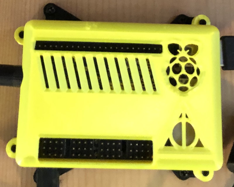
For the Raspberry Pi I found this case by jferguson368 which was made for the Pi and the AdaFruit Servo Hat. I printed it and was planning on using it but realized that it didn’t have an opening for the passthrough pins, but only for the servo pins. I still use the base part as is but I modified his design of the top and added a bit of flair to it as well.
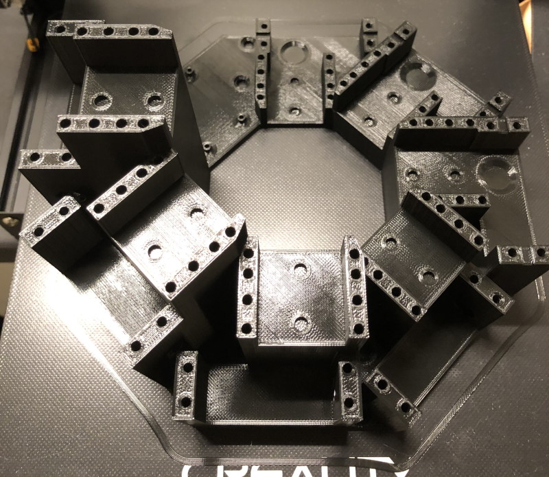
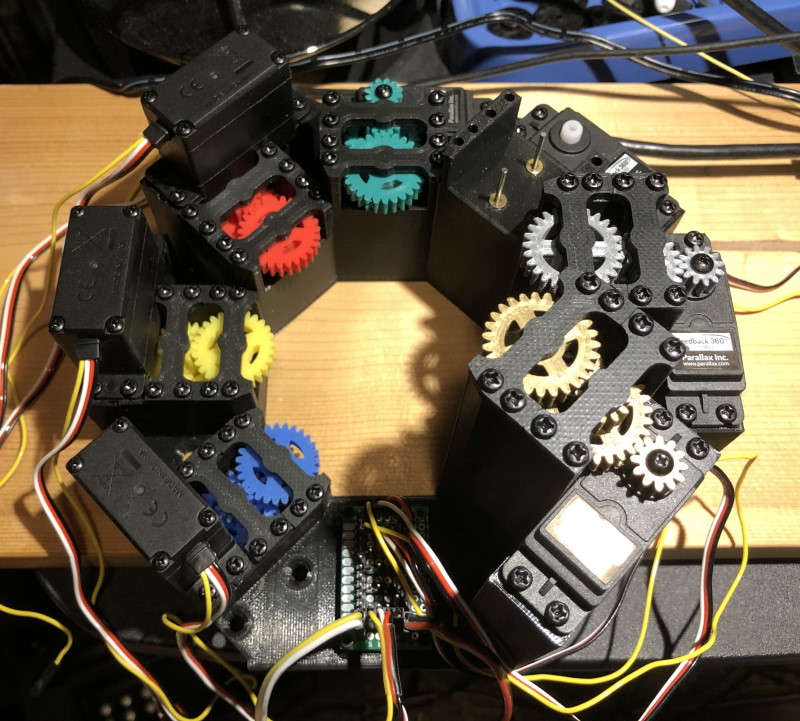
Servo Bracket #
This was the most complicated thing I have 3D printed but I am very happy with the result. Without all of the features, I would not have been able to get the gears and servos to fit.
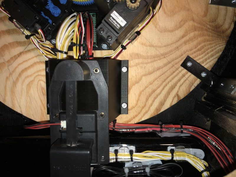
Pendulum Bracket #
Initially, I was going to mount the pendulum mechanism directly to the back of the clock face. However, the speaker was in the way and it would be hard to route the servo wires. So I create this bracket to allow the servo wires to pass under it.
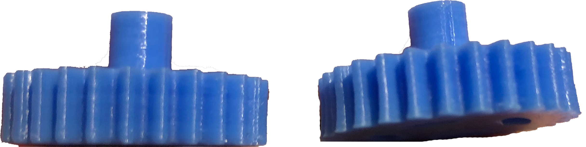
Gears #
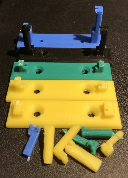
The gears were discussed in an earlier article but here are some tips in regards to 3D printing them. When 3D printing I print directly on the build surface. This tends to cause the first layer to be slightly larger due to the plastic oozing out a little bit. Normally this doesn’t affect the part enough to care or it is easily trimmed off with a razor. However, in the case of the gear this extra amount made it so the gears did not fit together quite right and because of all the teeth it was difficult to trim off. So for the gears instead of printing direcly on the build surface, I had the slicing program generate the build on a “raft”. essentially this build a surface up for the part to be built on top of. It does make the side of the gear touching the raft a bit rough but it eliminates the extra oozing in the first layer of the gear. See picture below. The one on the right has a slight curvature to the first few layers.
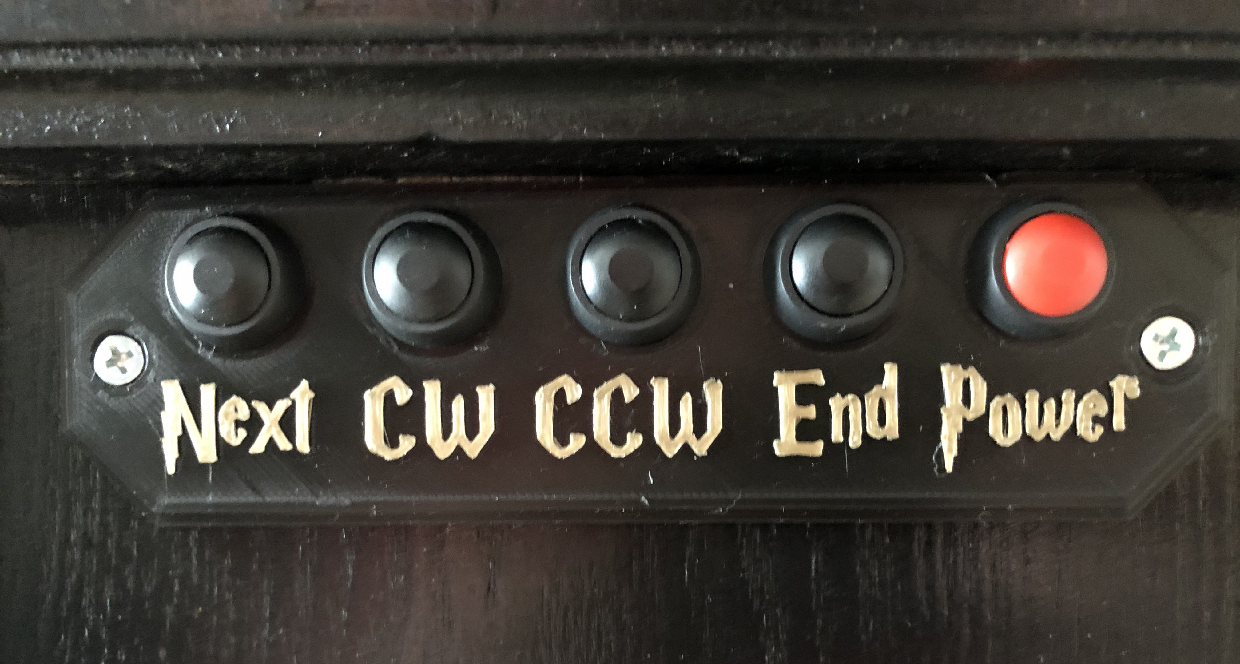
Calibration Button Plate #
More will be discussed when I get to the calibration. But there was a need for buttons for the user to use to position the hands to a known position on startup. This was due to the gear ratio maiking it so there are fifteen (15) zero degree positions around the clock. The Button Plate hold the buttons in place and has a label for the use of each button (using the HP font).
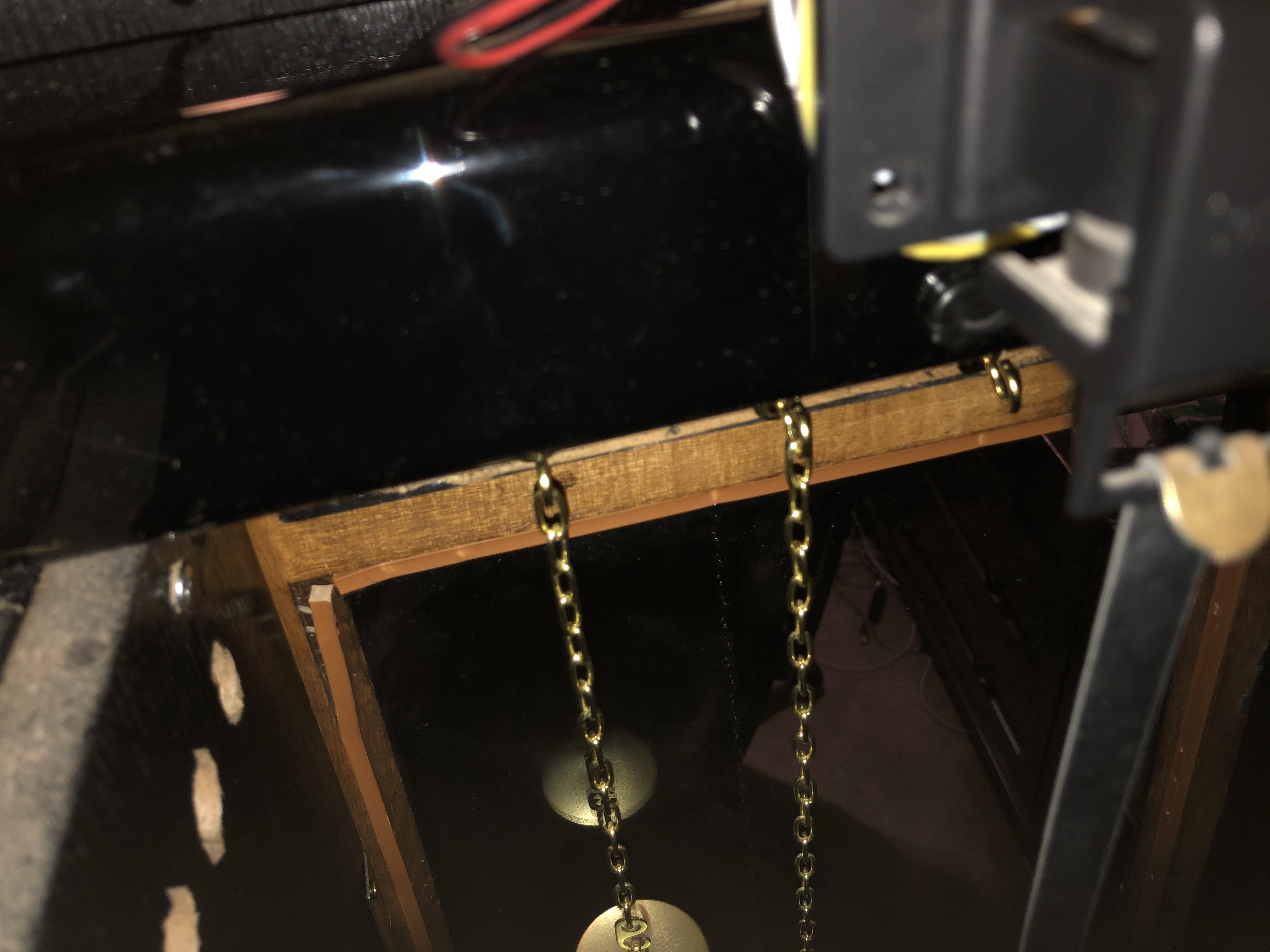
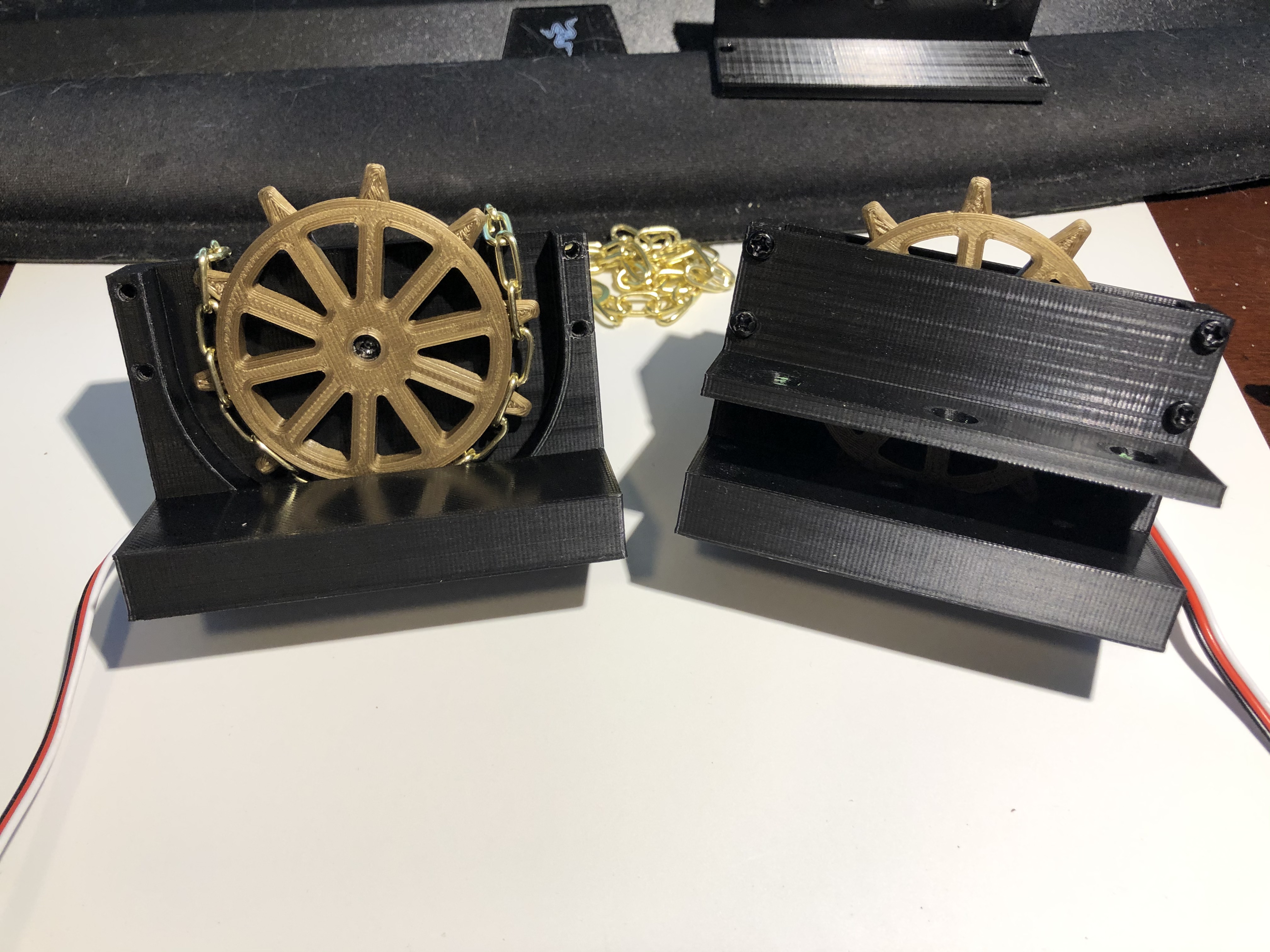
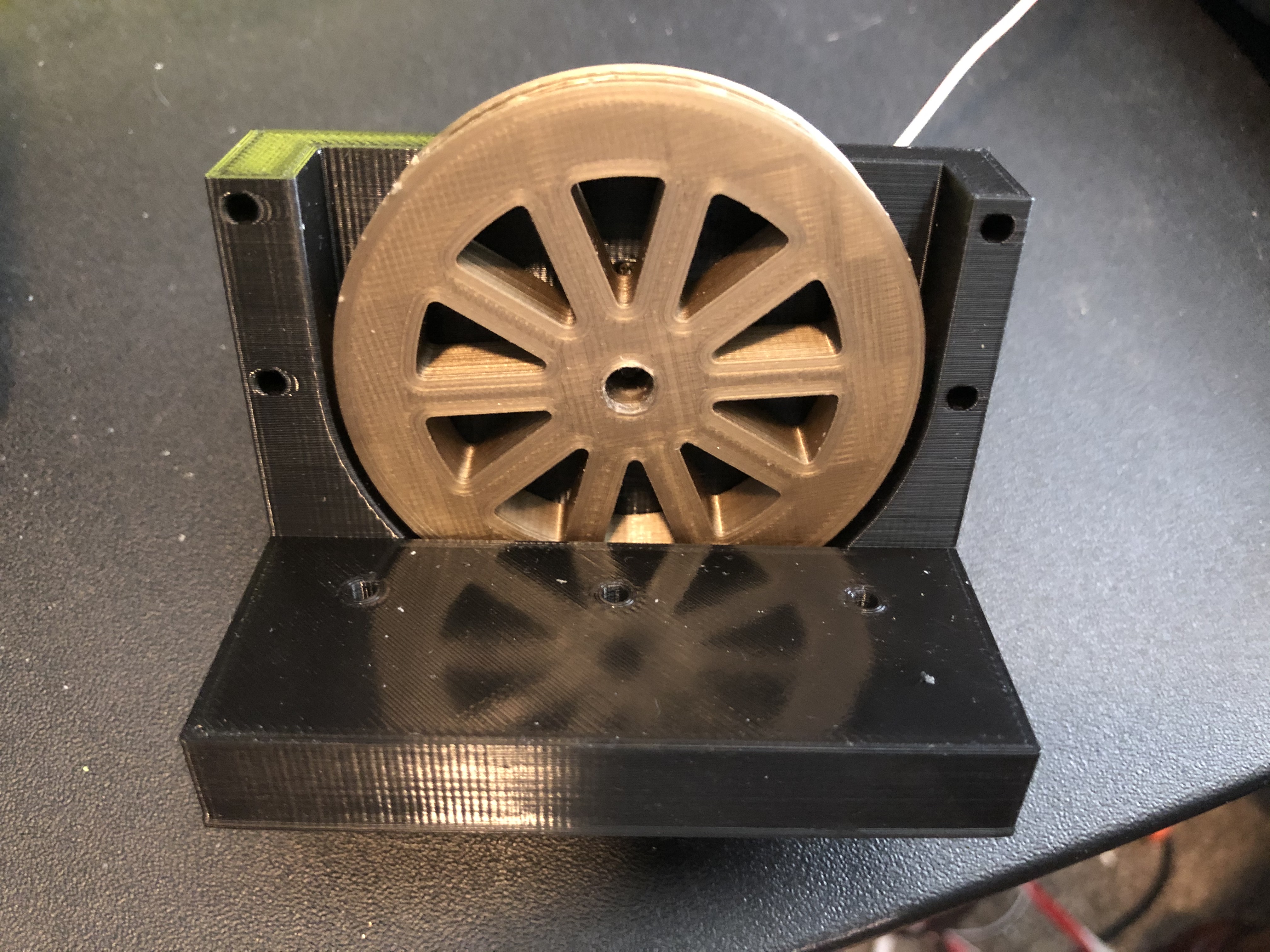
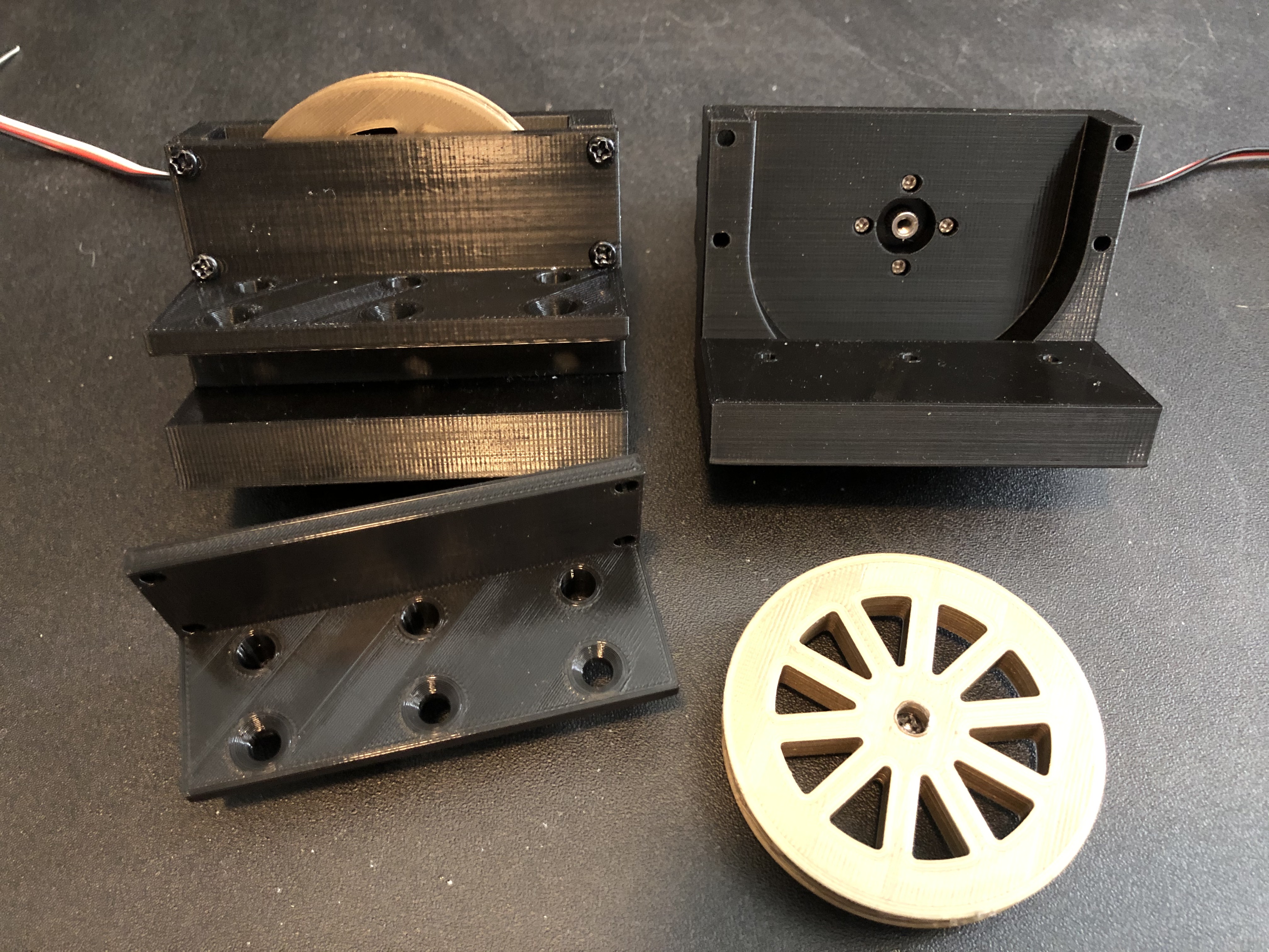
Weight Servos #
The weights were originally attached with screws and did not move. I went through many iterations of the design to try and use the chain and eventually replaced the chain with a ball change. The brackets were specifically designed to fit the servo and the lip of wood inside the clock.