


Parallax 360° High Speed Servo Feedback Requirements #
The Parallax 360° High Speed Servo is a continuous rotation servo and is controlled as such. However, it also has a feedback line that is also a PWM with the following specifications, (from the documentation, pg.3-4):
The servo sends a feedback output signal to your microcontroller via the yellow wire connection. This signal, labeled tCycle in the diagrams and equations below, has a period of 1/910 Hz (approx. 1.1 ms), +/- 5%.
Within each tCycle iteration, tHigh is the duration in microseconds of a 3.3 V high pulse. The duration of tHigh varies with the output of a Hall-effect sensor inside of the servo. The duty cycle of this signal, tHigh / tCycle, ranges from 2.9% at the origin to 91.7% approaching one clockwise revolution.
The Duty cycle corresponds to the rotational position of the servo, in the units per full circle desired for your application.
For example, a rolling robot application may use 64 units, or “ticks” per full circle, mimicking the behavior or a 32-spoke wheel with an optical 1-bit binary encoder. A fixed-position application may use 360 units, to move and hold the servo to a certain angle.
The following formula can be used to correlate the feedback signal’s duty cycle to angular position in your chosen units per full circle.
Duty Cycle = 100% x (tHigh / tCycle). Duty Cycle Min = 2.9%. Duty Cycle Max= 91.7%.

AdaFruit Servo Hat #
The AdaFruit Servo Hat mounts on the Raspberry Pi and provides both power and control for up to 16 servos. These hats are stackable up to 62 high to control an amazing 992 servos. (AdaFruit Website Link.)
This hat also allows pass-throughs of several GPIO pins. My though was that this would be perfect. The hat would allow control and power and the passthrough would allow for the feedback line.
Following the example MediaMongrels’ Democracy Bot and using their library for PCA9685 (the servo controller on the AdaFruit Servo Hat), I was able to control the servos in LabVIEW Community Edition pretty easily. I then implemented the code to calculate the angle from the feedback line in LabVIEW. The code worked fine, however, the angles were very jittery and jumpy. Just not accurate enough to do the precise control I wanted.
Why was it Not Accurate? #
This question stems from what a PWM signal is. A PWM signal is a ratio of how long in the cycle is the signal high compared to how long in the cycle is the signal low. For this particular feedback line from the internal Hall-effect sensor, when the signal is high only 2.9% of the time the position is at 0° and when the signal is high 91.7% of the time the position is at 359°.
I needed to be able to accurately measure the amount of time the signal was high compared to how long it is low. I found that in the middle of the range I could get pretty good results but below 20° and above 340° I would miss a falling or rising edge and then the calculation would be wrong.
After some investigation I determined that the Raspberry Pi was just not fast enough to get the 910Hz rate to calculate the Duty Cycle. It would definitely have trouble when I implemented all seven servos I wanted for this project. I needed a different way to read that signal.
The Arduino Due #
I decided I could still use the Raspberry Pi for the main application and the Servo Hat to power and control the servos but use something else for the feedback lines. After some internet searching, I did find a controller I could use to read the signal. It is the Arduino Due. It has 12 PWM channels that have a frequency of 1000Hz. I began working with it and still had trouble with accuracy. The angle measure would jump around about ±10°. This would not work when 1 second on the clock is 6°
Three Ways To Read A PWM Signal With Arduino #
I found the article, “Three Ways To Read A PWM Signal With Arduino” by Ben Ripley very helpful. In it he describes three ways to read a PWM signal:
- Using the pulseIn() Function
- Using External Interrupts
- Using Pin Change Interrupts
Option 1 #
Until now I have only been using the pulseIn() Function method because that was how the Parallax Servo documentation did it. However, because of the poor accuracy I tried the other two on the Arduino Due.
Option 2 #
Option 2 worked really well but as stated by Ripley, “Using attachInterrupt allows for greater efficiency but now we are forced to use pins 2 and 3 to read the PWM values and we are limited in the number of interrupts we can specify.” I wanted the Arduino Due to read all seven feedback lines.
Option 3 #
Therefore, I began using Option 3. For one servo the accuracy was great the jitter was less than ±1°. Then I added another servo. The accuracy went down but it was still acceptable at around ±3°. However, when I added a third servo, the accuracy dropped to ±15°. I wondered why until I realized that the interrupts were interrupting each other.
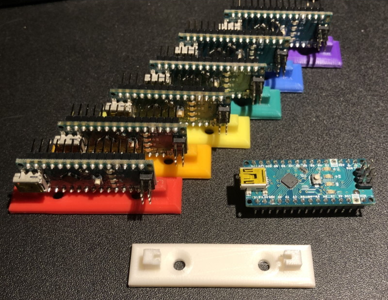
The Arduino Nano #
So, what to do now? Well, I decided that if the accuracy was great with one Arduino reading the feedback on one servo; I should get an Arduino for each servo. This seemed like overkill to have seven Arduino Dues and even Arduino Unos was too much; therefore, I settled on the Arduino Nano. I also decided to offload the servo control to the Arduino Nano as well. This made the architecture of my application simpler by allowing the Raspberry Pi to send the angle to the Arduino Nano and have it control the servo and calculate the feedback angle.
So, I bought seven Arduino Nanos and began programming them. Turns out the easiest to implement was again Option 1 and it provided accuracy of about ±3°. I probably would have investigated Option 2 except at this time I also decided that the servos moved too fast and I would have to design a gear box to slow it down. I ended up with a 15:1 gear ratio making a 15° turn on the servo equal 1° on the clock face. This translates to a 90° turn on the servo equal to a 6° turn, or 1 second for the Second Hand. Therefore, a ±3° accuracy on the servo translates to a ±0.2° accuracy on the clock face. I decided this would work for me.
I needed to select a gear ratio for my servos that would serve two purposes: first, to slow the hands down to make them move more like the Weasley Clock in the movie and, second, to help in mounting all of the servos so they fit on the back of the clock face.