
Arranging the Servos #
There is no way to directly drive each hand with the servo unless each hand was placed at a different location. However, that is not how clocks usually work anyway. A traditional clock has a timing control chip with oscollating quartz crystal that causes the gears to move. The gears are set up to transfer that movement through concentric shafts to the clock hands. In my case the servos are the source of the movement causing gears to move and there are seven concentric shafts for each of the seven hands. It quickly became an issue of how to fit seven servos behind the clock face to control all seven hands.
Nested Shafts #
In order to control seven (7) hands on this clock I had to find seven shafts that could nest inside each other. Luckily, K & S Engineering make some brass rods and tubes that work for this and I was able to buy them at Hobby Lobby. The sizes needed are as follows:
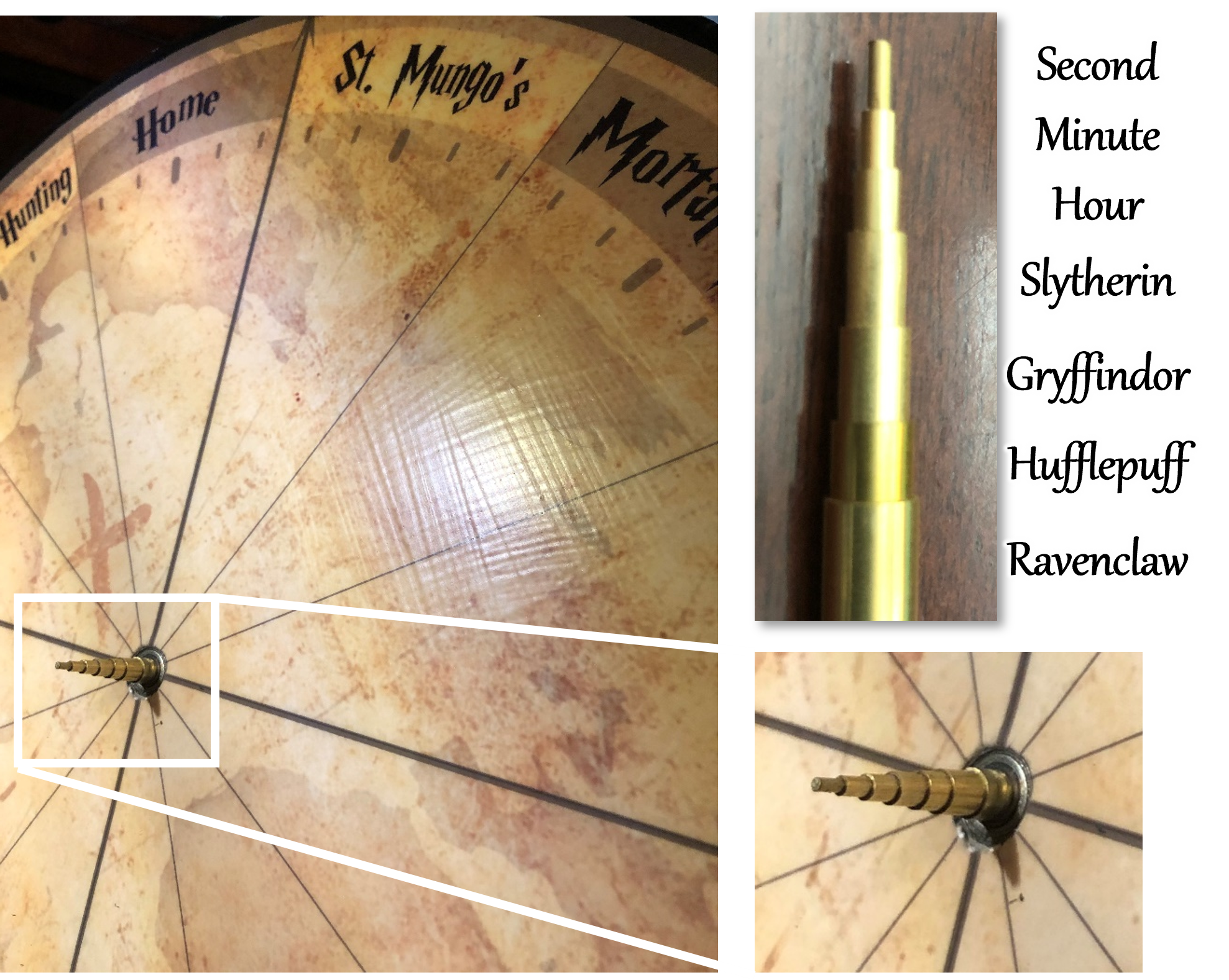
The shafts are made from brass tubes and a brass rod with sizes that allow them to fit inside each other. Each cut to length to allow for the driving gear to be attached to one side and the hand to be attached to the other. The sizes are as follows:
| OD | ID | Type |
|---|---|---|
| 1/16 | Rod | |
| 3/32 | 1/16 | Tube |
| 1/8 | 3/32 | Tube |
| 5/32 | 1/8 | Tube |
| 3/16 | 5/32 | Tube |
| 7/32 | 3/16 | Tube |
| 1/4 | 7/32 | Tube |
All dimensions in inches
OD = Outer diameter
ID = Inner diameter
Selecting the Gear Ratio #
Each servo would need to be placed around the shafts and use a series of gears to drive the shaft. The simplest gear setup to use to accomplish this would be two identical gears, one connected to the servo and one connected to a shaft. This would provide a 1:1 gear ratio. This could work but I figured I could make improvements by selecting a different gear ratio.
I needed to select a gear ratio for my servos that would serve two purposes:
- to slow the hands down to make them move more like the Weasley Clock in the movie
- to help in mounting all of the servos so they fit on the back of the clock face.
There are many resource online already for calculating a gear ratio. It gets a little more difficult if you want to have multiple steps, or compound gears. A good video tutorial that helped me can be found on YouTube, here.
I arbitrarily chose a 15:1 gear ratio because it made the math between the servo and the clock face easier, that is 15° on the servo equals 1° on the clock face. The math for each increment is as follows:
Time Hand Rates #
| Increment | Degrees on Clock Face | Degrees on Servo |
|---|---|---|
| 1 Second | 6° / second | 90° / second |
| 1 Minute | 1° / 10 seconds | 15° / 10 seconds |
| 1 Hour | 1° / 2 minutes | 15° / 2 minutes |
Location Hand Positions #
| Location | Degrees on Clock Face | Degrees on Servo |
|---|---|---|
| Mortal Peril | 0° | 0° |
| Quidditch | 30° | 450° (1.25 Rotations) |
| Work | 60° | 900° (2.5 Rotations) |
| Theatre | 90° | 1350° (3.75 Rotations) |
| Traveling | 120° | 1800° (5 Rotations) |
| Lost | 150° | 2250° (6.25 Rotations) |
| School | 180° | 2700° (7.5 Rotations) |
| Holiday | 210° | 3150° (8.75 Rotations) |
| Church | 240° | 3600° (10 Rotations) |
| Treasure Hunting | 270° | 4050° (11.25 Rotations) |
| Home | 300° | 4500° (12.5 Rotations) |
| St. Mungo’s | 330° | 4950° (13.75 Rotations) |
This made the speed better. The Parallax 360° High-Speed Servo is just that, a high-speed servo. It works better at near-full to full speed which is 2 rotations per second or 120 Rotations Per Minute (RPM). I experimented with reducing the speed and as it nears its dead zone, “stop”, point; it could lock up as it has not reached the desired angle yet but the speed is too slow to allow the servo to actually move any more.
At top speed, applying the gear ratio, reduces to 8 RPM or 1 rotation every 7.5 seconds.
Constraints #
The other constraints I had in my gear box include:
- The smallest gear I could 3D print and fit the servo’s shaft is 12 teeth at a 30 tooth/inch pitch. (Determined through experimentation with a 0.4 mm nozzle on my 3D printer.)
- I needed the gears to not interfere with the servo mounting points.
- I needed the gear attached to the main clock shafts be large enough to allow mounting all of the servos around it.
My first attempt to do this was with Lego™ gears, but after I got my Ender 3 Pro 3D printer, I was able to create my own custom gears. It could be possible to use Lego™ gears but either the ratio or the number of gear steps would have had to change.
Outcome #
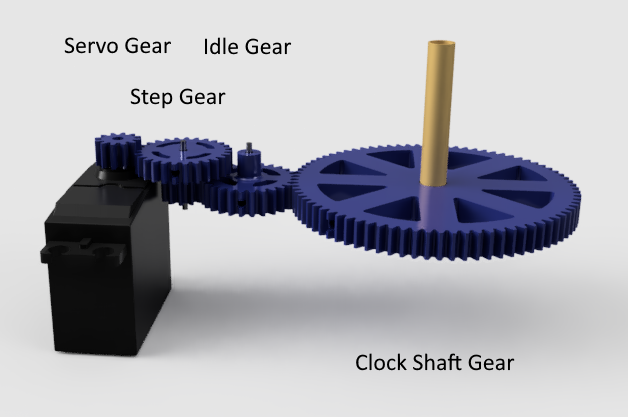
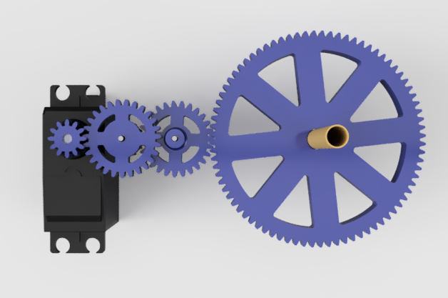
The outcome was that I needed 2 steps to make the ratio and the size of the gear on the clock shaft would depend on how far the servo is from the clock shaft. To enable that, an idle gear would also be used. The ratios came out as follows:
| First Gear | Second Gear | Ratio |
|---|---|---|
| 12 Teeth | 27 Teeth | 4:9 |
| 12 Teeth | 80 Teeth | 3:20 |
| Total Ratio | 1:15 |
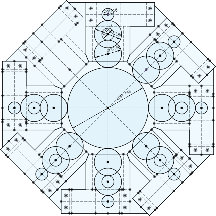
The idle gear was also made to be 27 teeth to fit in the same fixture as the step gear. As can be seen below, all seven servos fit and an eighth servo could fit as well. I modelled the gears, fixtures and checked the spacing using Fusion 360, which is free for non-commercial use.
This configuration allows for all seven servos to be mounted around the clock shaft as follows: