I was completely new to the world of selecting a servo. How do I command it to turn? For my project I also needed to know the position. What servos exist that allows me to set the position or at least get the position back as a output. Turns out there are a lot of options.
I wanted a servo to control the hands of my Weasley Clock. I needed a servo that could continuously turn and cover the full 360°. I also wanted to be able to set the position within 3° because to a second hand on a clock travels at 6° per second.
For a position servo, the signal sent to it sets the absolute position. Setting and holding the the signal sets and holds the position. Most position servos have a limited range. The most common being able to turn from -90° to +90°. I have seen others that can do a variety of ranges but most are limited to between 0° and 270°. These are great for robotic application where full rotation is not needed but does not fit my requirements.
There are other options for position servos that can do a full turn or more. ppeters0502, in his tutorial, chose GWS S125 1T 2BB Sail Wench Servos that could do one complete rotation. There are other sail wench servos that can turn up to three and a half (3.5) rotations. These are usually used for model sailboat wenches to lift and lower the sails. This type of servo would work if the desired use was just for clock hands to point to locations, but I also want three of the clock hands to tell the time. I though it would be weird having the hands of my clock turning and reaching that limit, then having to reverse and spin backwards 3.5 turns.
For a speed servo, or continuous rotation servo, the signal represents the speed to set to. The servo will have some range where on one end of the range is the highest speed in one direction, at the mid-point (deadband range) it is stopped, and at the other extent it is the highest speed in the other direction.
To control a servo the signal sent to it depends on whether the servo is analog or digital.
Analog servos operate on voltage signals that come through as Pulse Width Modulation (PWM) signals.
Digital servos use a microprocessor to receive commands as high frequency voltage pulses.
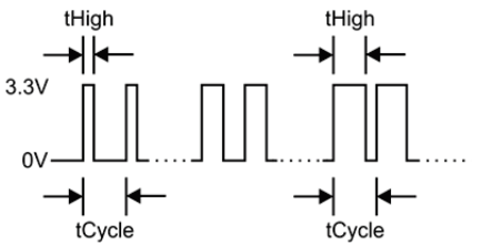
Most of the servos I have dealt with are analog servos and use a PWM signal. A PWM signal is varied by its Duty Cycle.
Duty Cycle
Duty Cycle
The duty cycle is a calculation of what percentage of the cycle time it high versus low. Zero percent (0%) is all low, where one-hundred percent (100%) is all high.
It’s rare that a servo can use the full range from 0% to 100% completely, therefore it usually stops before the extreme ranges. The duty cycle then represents motion range of the servo.
For position servos, for example, if the servo has a range of 180° (-90° to 90°) then close to 0% would be -90° and close to 100% would be 90°.
For continuous rotation servos close to 0% would be full speed counterclockwise and close to 100% would be full speed clockwise with a deadband (“stop”) range somewhere in the middle.
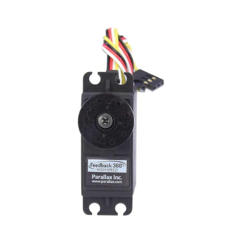
So for my application, it sounds like I need a continuous rotation servo but I still need to know the position. I thought about adding my own sensors but realized if I wanted one at every second position, I would need 60 sensors per hand. That seemed like too much wiring and programming. Eventually I did find one servo that was a continuous rotation servo and had a built-in Hall Effect Sensor conntected to a feedback line. This is the Parallax 360° High Speed Servo and it is the one I selected for this project.
This servo fulfilled my requirements of having continuous rotation but also being able to get feedback of the position. It is bidirectional with a speed of -140 RPM to 140 RPM. Its PWM range has 1280μs to 1480μs for clockwise motion, 1480μs to 1520μs for stop, and 1520μs to 1720μs for counterclockwise motion. Its feedback line gives a PWM signal at 3.3V and 910Hz with a duty cycle minimum of 2.7% representing 0° to the duty cycle maximum of 97.1% representing 359°. (See the Parallax 360° High Speed Servo whitepaper here.)
Weasley Clock Project -
This article is part of a series.